
Ship Handling // Hydrodynamics & Vessel Manoeuvring
The Pivot Point of a Ship: Hydrodynamics, Migration Physics, Turning Lever Arms, and Tug Assistance
A comprehensive technical guide to the Pivot Point (apparent center of rotation) in naval architecture and practical ship handling. Analyzing the mechanical distinctions between the Center of Gravity (G), the Center of Lateral Resistance (CLR), dynamic pivot migration during headway and sternway, calculating tug turning moments, and understanding why bow thrusters experience sharp thrust decay at speed.
The Pivot Point (PP) is a theoretical point on the vessel’s longitudinal centerline about which the ship appears to rotate when viewed by an outside observer during a turning manoeuvre. Kinematically, it represents the exact point along the centerline where transverse drift velocity relative to the water is zero.
Unlike the physical Center of Gravity (G), the Pivot Point is not a fixed structural location. Its position migrates dynamically along the hull based on vessel speed, motion direction (ahead vs. astern), underwater hull form, dynamic trim, and external forces applied by tugs or thrusters.
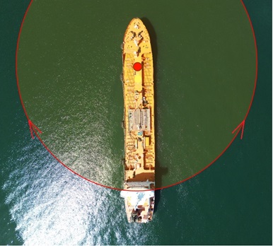
1. Mechanical Foundations: Distinguishing G, CLR, and Pivot Point
In practical seamanship and naval architecture—as examined in Notes on Shiphandling and foundational treatises like Basic Ship Theory—navigators must differentiate between three distinct points:
- Center of Gravity (G): The point through which the vessel’s total weight acts vertically downward. Linear momentum and translational accelerations occur through G;
- Center of Lateral Resistance (CLR): The geometric centroid of the submerged profile of the hull. It is the focal point where the resultant hydrodynamic water force opposes lateral drift. On an even keel at rest, it lies near amidships;
- Pivot Point (PP): The apparent axis of rotation resulting from the balance between the ship’s longitudinal momentum and the hydrodynamic resistance wedge built up against the hull. All rotational turning moments are measured with reference to the Pivot Point.
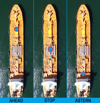
2. Dynamic Migration of the Pivot Point Across Operational Regimes
Hydrodynamic resistance forces shift the Pivot Point across distinct operational phases:
| Operating State | Pivot Point Location on Centerline | Hydrodynamic Mechanism | Tactical Consequence for the Navigator |
|---|---|---|---|
| 1. At Rest (Dead in the water) | Near Amidships (≈ 0.5 L from bow, close to G). | Zero hydrodynamic water resistance. The ship behaves like a free rigid body in fluid. | Equal lateral forces applied symmetrically at bow and stern produce pure parallel bodily drift without yaw. |
| 2. Steady Headway (Making headway) | ≈ 1/4 L to 1/3 L from Forward Perpendicular (FP). | The bow encounters undisturbed water, creating a high-pressure hydrodynamic resistance wedge forward of amidships. | The lever arm for bow forces contracts sharply, while the lever arm for stern forces expands to nearly 3/4 of the ship’s length! |
| 3. Steady Turning Circle (Underway) | ≈ 1/6 L to 1/5 L from the stem. | The vessel settles into a constant drift angle β. The bow stays inside the path while the stern kicks vigorously outward. | The stern sweeps through a wide arc (“stern kick”), demanding extensive clearance when turning away from berths or buoyed channels. |
| 4. Making Sternway (Going astern) | ≈ 1/4 L from Aft Perpendicular (AP). | Hydrodynamic resistance transfers to the transom and run of the hull aft, shifting the resistance wedge astern. | The bow attains a massive lever arm (≈ 3/4 L), making the vessel highly sensitive to windage and forward tug pulls. |
3. Berthing Operations: Tug Assistance and Moment Calculations
Failing to account for the position of the Pivot Point when directing tugs is a frequent cause of heavy contact during harbor manoeuvres, as documented in marine pilotage guidelines and standard Marine Pilotage Procedures.
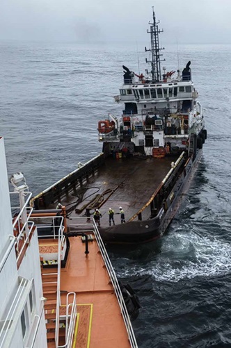
Consider a vessel of length L = 200 m entering a fairway at 4 knots. The Pivot Point shifts forward to 1/4 of the length from the bow—meaning it is positioned 50 m from the bow and 150 m from the stern.
- Forward Tug (40-tonne bollard pull): The lever arm to the Pivot Point is only L1 = 50 m. Resulting turning moment: M1 = 40 t × 50 m = 2,000 t·m;
- Aft Tug (40-tonne bollard pull): The lever arm to the Pivot Point is L2 = 150 m. Resulting turning moment: M2 = 40 t × 150 m = 6,000 t·m!
Practical Rule: While making headway, an aft tug is 3 times more effective at yawing the vessel than a forward tug of equal power!
When the vessel moves astern, the Pivot Point migrates into the aft quarter (50 m from the stern and 150 m from the bow).
- The aft tug loses its turning lever arm (shortened to 50 m) and can primarily act to brake speed or haul the stern sideways bodily;
- The forward tug gains an enormous 150 m lever arm, easily turning the bow against strong winds or tidal streams. Master-pilot interactions should be coordinated using standard forms like the Vessel Pilot Card Master-Pilot Exchange.
4. Why Bow Thrusters Lose Effectiveness When Making Headway
Ship handlers frequently notice that a bow thruster capable of pivoting a vessel effortlessly when stationary at a quay becomes virtually ineffective once the ship exceeds 3 to 4 knots.
1. Contraction of the Lever Arm via Pivot Migration: When stopped, the thruster acts against a Pivot Point at amidships with a lever arm of roughly 0.5 L. As the vessel makes headway, the Pivot Point migrates forward to near the bow (0.25 L), cutting the effective rotational lever arm in half!
2. Hydrodynamic Thruster Jet Deflection (Coanda Effect): At speeds above 2–3 knots, oncoming water bends the emerging transverse water jet back against the downstream hull plating. This creates a localized low-pressure suction zone on the opposite side of the turn, partially neutralizing the thruster’s lateral thrust.
At speeds exceeding 3 to 4 knots, course corrections should be executed using the rudder and main engine, relying on propeller wash over the rudder blade rather than the bow thruster.
5. Influences of Trim, Shallow Water, and Dynamic Squat
Operational trim and restricted under-keel clearance (UKC) alter the hydrodynamic pressure distribution across the hull:
- Trim by the Stern: Increases submerged lateral profile area aft, moving the Center of Lateral Resistance (CLR) and the Pivot Point slightly further aft. This improves directional course stability but increases the tactical turning diameter;
- Trim by the Head: A hazardous condition. The Pivot Point shifts abnormally far forward toward the stem. The rudder’s turning lever arm reaches an extreme maximum, rendering the ship directionally unstable (“yaw-prone”) and sluggish to check swings;
- Shallow Water Effect & Squat: In restricted water depths, restricted return flow beneath the keel induces dynamic squat—computable with our Ship Squat Calculator. The buildup of water cushions around the hull expands the tactical turning circle diameter by 1.5 to 2 times compared to deep-water sea trials. Review critical clearance requirements in the Under-Keel Clearance Calculation Guide.
Frequently Asked Questions: Pivot Point of a Ship (FAQ)