
Naval Architecture // Hydrostatics & Stability
Ship Intact Stability: Fundamentals, Equilibrium States, Metacentric Height (GM), Righting Lever (GZ), and Longitudinal Stability
A comprehensive engineering and nautical guide to the intact stability of commercial ships. Exploring the hydrostatic relationship between Center of Gravity (G), Center of Buoyancy (B), and Metacenter (M), the physics of righting moments, Free Surface Effect (FSE) mitigation, stable versus unstable equilibrium, and the crucial distinction between transverse and longitudinal stability.
- Intact Stability: The stability of a sound, undamaged hull structure with all internal compartments, cargo holds, and double bottoms free of sea water flooding under designed cargo, fuel, and ballast conditions;
- Damage Stability: The survival capacity of a compromised hull following underwater breach or compartment flooding, evaluating residual buoyancy, asymmetric heel angles, progressive downflooding, and final waterline equilibrium (to verify draft and trim marks, refer to our operational guide on under keel clearance calculation).
Damage stability scenarios cannot be evaluated without an accurate understanding of intact statics. Correct bridge stability calculations on every commercial voyage determine whether a vessel safely withstands heavy weather, adhering to principles detailed in Basic Ship Theory.
The Four Reference Points of Ship Hydrostatics: K, B, G, and M
The geometric foundation of transverse intact stability relies on the relative vertical positioning of four fundamental points referenced from the molded baseline (keel plate — K):
The datum plane from which all vertical hydrostatic dimensions are measured: height of the center of gravity (KG), center of buoyancy (KB), and transverse metacenter (KM).
The geometric centroid of the submerged underwater hull volume. The total upward buoyant force acts through point B, pointing vertically upward with a magnitude equal to the weight of displaced water. As the ship heels, the geometry of the submerged hull changes (the immersed wedge adds volume while the emerged wedge loses volume), shifting point B toward the low side to position B1.
The single point through which the downward gravitational force of the vessel and all onboard weights (lightship, deadweight, fuel, ballast, cargo, and stores) acts. The position of point G is governed entirely by weight distribution and remains fixed during roll motions, provided internal cargo is secured and tank fluids do not shift.
The intersection of the vertical line of action of the buoyant force through B1 with the centerline plane during small angles of heel (up to approximately 10–12°). Physically, point M represents the instantaneous center of curvature about which the ship rotates during rolling oscillations.
The Three States of Equilibrium: Righting and Capsizing Moments
Depending on the vertical relationship between the Center of Gravity (G) and the Transverse Metacenter (M), a floating ship demonstrates one of three equilibrium conditions:
1. Stable Equilibrium (GM > 0, Positive Metacentric Height)
Stable equilibrium exists when the Center of Gravity G lies vertically below the transverse metacenter M (KG < KM). When an external moment heels the vessel to an angle θ, the center of buoyancy shifts outward from B to B1.
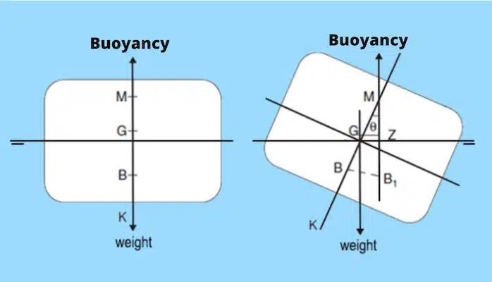
Because point G is below M, the upward buoyant force acting through B1 passes to the low side of the downward gravity vector. The horizontal distance separating these opposing vectors is the righting lever (GZ), producing a Righting Moment (Mrighting):
This couple acts to rotate the vessel back toward the upright position once the external force ceases. The ship is stable.
2. Neutral Equilibrium (GM = 0, Zero Stability)
Neutral equilibrium occurs when the vertical position of G coincides with metacenter M (KG = KM). As the hull heels, the line of action of the buoyant force passes directly through the center of gravity.
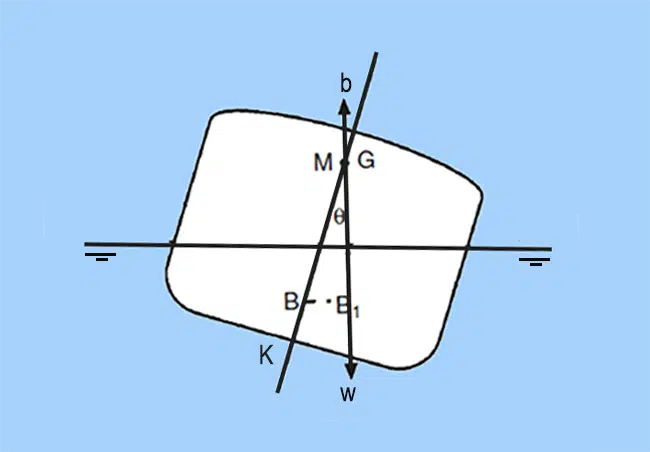
Because there is no horizontal separation between the vectors, GZ is zero. Neither a righting moment nor an upsetting moment is generated. If heeled by a gust of wind, the ship comes to rest at the new heel angle without attempting to right itself.
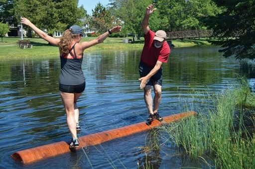
3. Unstable Equilibrium (GM < 0, Negative Initial Stability)
Unstable equilibrium occurs when the Center of Gravity G rises above the metacenter M (KG > KM). This hazardous condition can arise from high deck cargo stowage, topside ice accumulation, or cargo shift.
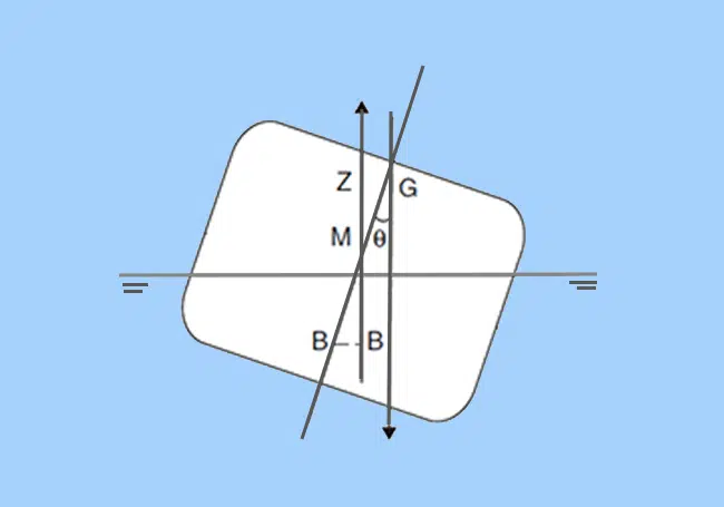
When heeled, the line of buoyant force passes inside the line of gravity, generating a negative righting arm (capsizing lever −GZ). Rather than righting itself, the ship heels further until the submerged hull flare increases the waterplane area enough to push metacenter M above G (reaching the Angle of Loll), or capsizes entirely.
Stability Hazard: Free Surface Effects and the GZ Curve
Initial metacentric height GM is reliable only for small inclinations (up to 10–12°), where metacenter M remains virtually stationary on the centerline. For larger angles, naval architects evaluate the GZ Curve (Curve of Statical Stability), plotting righting arms across the full range of heel up to the angle of vanishing stability.
When a liquid cargo, ballast, or fuel tank is slack (partially filled), the liquid shifts toward the low side when the vessel heels. This internal weight migration acts as a virtual rise of the ship’s center of gravity, reducing effective metacentric height by a free surface correction δGM (FSC):
where i is the transverse second moment of area of the liquid surface (for a rectangular tank: i = l × b³ / 12), and ρ is liquid density.
Note that tank breadth (b) is cubed in this formula. A wide centerline tank without a longitudinal swash bulkhead produces nine times more free surface loss than two separated wing tanks of half the width.
IMO 2008 Intact Stability Code Mandatory Criteria:
- Fluid metacentric height (GMfluid) corrected for free surfaces must not be less than 0.15 m for general cargo ships (and not less than 0.10 m for timber deck cargo carriers);
- The maximum righting arm (GZmax) must occur at a heel angle preferably exceeding 30°, but never less than 25°;
- The righting lever GZ must be at least 0.20 m at an angle of heel equal to or greater than 30°;
- The area under the GZ curve must be at least 0.055 meter-radians up to 30°, and at least 0.090 meter-radians up to 40°.
Test shipboard parameters dynamically using our online Ship Stability Simulator (GZ Curve).
Longitudinal Stability: Why Vessels Do Not Pitchpole
While the earlier sections focused on transverse stability (rolling around the longitudinal axis), vessels are also subjected to fore-and-aft trimming moments caused by longitudinal weight movements:
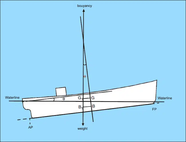
During pitch motions and trim changes, rotation occurs about the longitudinal metacenter (ML). The vertical distance between the Center of Gravity and the longitudinal metacenter is the longitudinal metacentric height (GML).
| Characteristic / Parameter | Transverse Stability (Athwartships) | Longitudinal Stability (Fore-and-Aft) |
|---|---|---|
| Motion / Inclination Type | Heel and Roll (Port / Starboard) | Trim and Pitch (Bow / Stern) |
| Governing Metacenter | Transverse Metacenter (M) | Longitudinal Metacenter (ML) |
| Typical Metacentric Height | 0.30 – 2.50 meters | 100 – 250 meters (approximately vessel length Lbp) |
| Capsizing Danger | High: rolling past GZmax causes capsize | Negligible: the vessel resists pitch inclination with massive force |
| Primary Operational Concern | Preserving life and structural uprightness | Controlling draft, propeller immersion, and Under Keel Clearance |
Because a ship’s length is 6 to 8 times greater than its breadth, the longitudinal second moment of area of the waterplane is immense. As a result, GML is typically 100 to 120 times larger than transverse GM. Under normal operations, commercial vessels cannot capsize end-over-end (pitchpole), which is why shipboard stability control concentrates almost entirely on transverse stability.
Explore how hydrodynamic hull lines affect displacement in our review of the Block Coefficient of a ship, calculate dynamic draft margins using the Ship Squat Calculator, and evaluate freshwater immersion with our DWA / FWA Calculator Online.