
Naval Architecture // Dynamics & Maritime Safety
Ship Dynamic Stability: Physics of Sudden Loads, External and Internal Heeling Moments
A comprehensive professional guide to ship dynamic transverse stability: how it fundamentally differs from static stability, why sudden moments pose severe capsizing risks, and how to analyze external forces (beam wind gusts, high-speed turning, heavy crane lifting, vessel grounding, and towline tension) alongside internal hazards such as free surface effects and cargo shifting.
What Distinguishes Static from Dynamic Stability?
In our technical analysis of Ship Intact Stability, we reviewed equilibrium conditions under the assumption that disturbing forces are applied gradually, causing the hull to heel smoothly until the righting moment matches the heeling moment.
In real seaways, however, disturbing forces act dynamically and instantaneously: a storm squall strikes within seconds, breaking seas impact the hull with massive kinetic force, or a towline snatches under heavy surge. When a heeling moment is applied suddenly, the hull accelerates, acquiring angular momentum and kinetic energy. Upon reaching the static angle of equilibrium where moments are equal, the vessel does not stop; rotational inertia causes it to roll beyond this point until all dynamic energy is dissipated by the work done by the righting moment.
When a constant heeling moment is applied suddenly (dynamically) to an upright vessel in calm water, the resulting maximum dynamic heel angle is theoretically approximately twice the static heel angle (θdyn ≈ 2 × θstat). Consequently, a ship capable of withstanding a steady wind pressure may capsize if struck suddenly by an equivalent wind gust.
Dynamic stability is quantified not merely by the righting lever arm, but by the work done by the righting couple (the area under the righting lever curve). Evaluating safety requires dividing heeling moments into two distinct classifications: external forces from the marine environment and internal forces originating within the vessel itself.
Type 1: External Heeling Moments
External moments originate from interactions between the hull and natural environmental forces or external maritime gear:
Transverse wind acts against the vessel’s above-water lateral profile, comprising topsides, accommodation superstructures, and deck container stacks. The resultant aerodynamic thrust acts through the center of lateral windage above the waterline, while hydrodynamic drag acts upon the underwater hull (governed by the vessel’s Block Coefficient Cb).
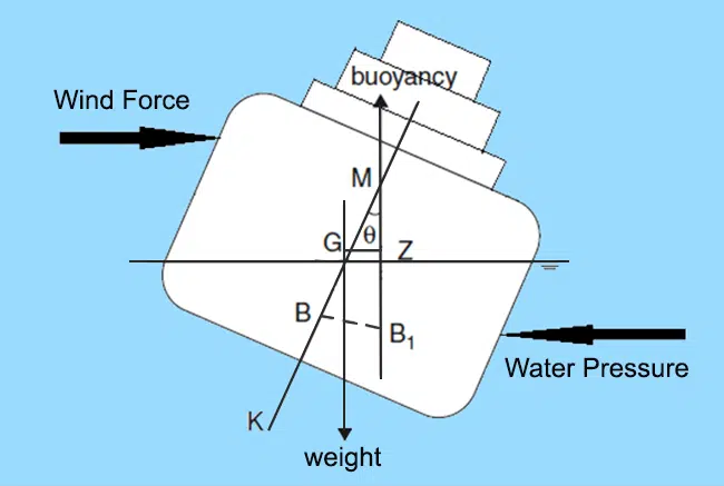
These opposing forces form a heeling couple with a vertical lever arm separating the center of windage from the center of lateral underwater resistance. The ship heels until its hydrostatic righting moment balances the wind moment. Under the IMO Weather Criterion (Code on Intact Stability, 2008), every merchant vessel must prove its ability to survive a sudden gust of wind occurring at the maximum roll amplitude toward the windward side.
When heavy project cargo or containers are handled using the ship’s own deck cranes or derricks, a hazardous shift occurs in the overall Center of Gravity of the ship-cargo system.
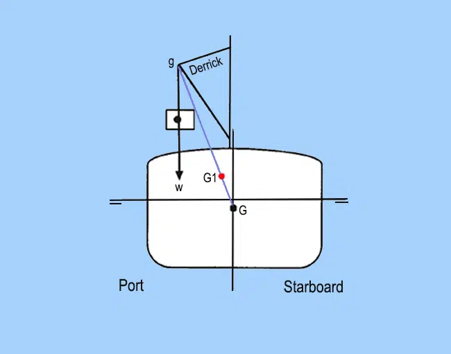
Governing Physical Law: The instant cargo is hoisted clear of the quay, its effective center of gravity transfers immediately to the crane jib head (boom tip), regardless of how close to the water or deck the load hangs. This creates a severe compound hazard:
• The vessel’s center of gravity shifts upward toward the boom head, decreasing metacentric height (GM);
• As the crane slews outboard, the center of gravity shifts athwartships, generating a large heeling moment toward the lifting side. Handling procedures should always adhere to guidelines set in Shipboard Crane Operator Certification.
When a vessel executes a rapid turn at sea speed, centrifugal acceleration induces an outward heeling couple (see rudder steering principles in Helmsman Watch & Steering Orders).
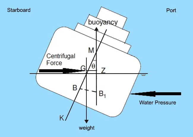
The horizontal centrifugal force acts through the vessel’s Center of Gravity (G), directed away from the turning center. Simultaneously, centripetal hydrodynamic water pressure acts against the submerged bilge on the inward side. This generates an upsetting moment that heels the ship away from the direction of the turn (e.g., turning hard to starboard causes an outward heel to port). The heeling lever is directly proportional to the square of the ship’s speed (V²) and inversely proportional to the turning circle radius (R).
When a vessel strands or contacts an underwater obstruction off-center, an upward reaction force (R) develops at the point of impact.
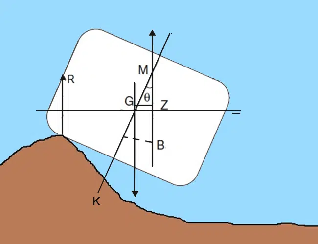
The upward reaction force R reduces the net buoyant force supporting the displacement to (Δ − R). In hydrostatic terms, this reaction behaves like the removal of an equivalent weight from the keel line, causing a severe virtual rise in the Center of Gravity. As the tide falls, R increases, accelerating loss of stability and causing the vessel to capsize over the grounding pivot. Navigators should monitor shallow margins using our UKC Calculator Online.
During alongside operations, excessive tension on mooring lines caused by passing wash or heavy tidal streams can impart steady heeling angles.
A far more critical risk exists for escort tugs. When a towing line leads broad on the beam of a tug while moving ahead, the transverse towline pull creates an extreme heeling moment known as girting (tripping). The towing point is situated high above the water, while the hydrodynamic resistance of the tug’s hull opposes the motion below, capsizing the tug within seconds unless the towline is tripped immediately. Mooring crews should review standard setups in our Mooring Operations Simulator Online.
Type 2: Internal Heeling Moments
Internal moments originate from shifting mass inside the hull. Unlike sudden weather events, internal shifts are typically manageable through proper operational practices:
Transferring liquids between wing tanks or the physical shifting of solid cargo transverse to the ship’s centerline displaces the overall Center of Gravity from point G to G1.
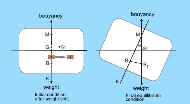
A horizontal separation is created between G1 and the initial Center of Buoyancy B. The vessel rolls until the newly submerged volume shifts the Center of Buoyancy to B1, aligning it vertically below G1. In severe seas, shifting of bulk dry cargoes (grain, iron ore fines) produces a permanent list, dangerously degrading dynamic righting energy on the listed side.
Partially filled (slack) ballast, fuel, or liquid cargo tanks represent one of the most common causes of stability degradation at sea.
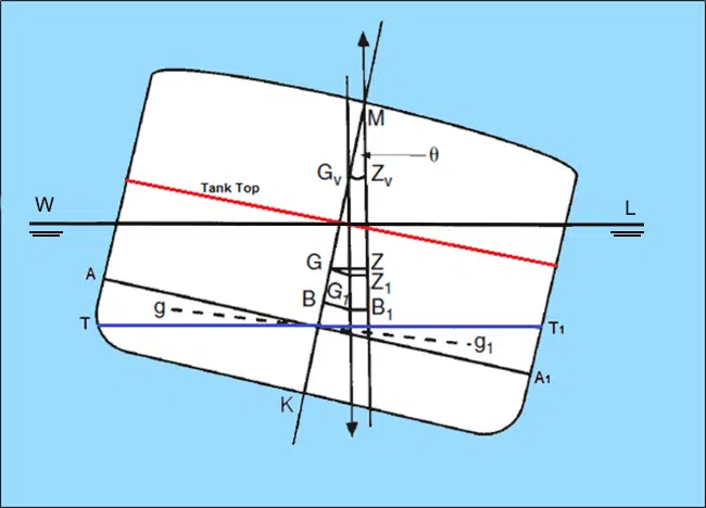
As the ship rolls, fluid inside a slack tank surges to the low side (volume wedge A-T moves to A1-T1). The local center of mass of the fluid shifts from g to g1. Consequently, the combined gravitational vector of the ship acts through a virtual Center of Gravity Gv, located significantly above the physical center G. The effective metacentric height shrinks to GvM, reducing the righting arm to GvZv and lowering resistance against capsizing. Tanker cargo distribution can be verified beforehand using Tanker Stowage Plan Software.
The Curve of Dynamic Stability: Work Done Against Overturning
While the statical stability curve (GZ curve) illustrates the magnitude of the righting arm at any given heel angle, the Curve of Dynamic Stability represents the integral of the GZ curve—denoting the cumulative work required to heel the vessel to that angle.
| Characteristic / Parameter | Static Stability Analysis | Dynamic Stability Analysis |
|---|---|---|
| Application of Load | Gradual, infinitely slow, quasi-static | Instantaneous, violent (wind gusts, rudder shifts) |
| Primary Physical Metric | Righting Moment: Mrighting = Δ × GZ | Dynamic Energy: Work = ∫ Mrighting dθ |
| Equilibrium Condition | Moment equality: Mheel = Mrighting | Energy equality: Area of Heeling = Area of Righting |
| Resulting Angle of Heel | Static heel angle θstat | Dynamic heel angle θdyn ≈ 1.5 – 2.0 × θstat |
| Primary Regulatory Metric | IMO GZ Curve criteria (2008 IS Code) | IMO Weather Criterion (Wind & Wave roll area) |
Never evaluate a maneuvering or windage situation based solely on static heel indicators. In rapid tactical turns or beam squalls, dynamic overshooting can submerge weatherdeck air pipes, cargo vents, or open openings, precipitating downflooding and catastrophic loss of buoyancy.
Review fundamental stability standards in our overview of STCW Convention Manila Amendments and analyze hydrodynamic sinkage during coastal pilotage using the Ship Squat Calculator.