Navigator Practice // Celestial Navigation
Marine Navigation Sextant: Complete Guide to Construction, Adjustments, and Index Error Calculation
A comprehensive step-by-step manual on handling and calibrating the marine sextant. Learn structural anatomy, eliminate the three primary adjustable instrument errors, and master index error verification using the horizon, stars, and the solar disk with Nautical Almanac quality cross-checks.
During cadetship and shore-based training, sextant mechanics are often covered only superficially, leaving many deck officers uncertain when conducting practical mirror adjustments at sea. This guide outlines the anatomy of the instrument, practical steps to eliminate internal errors, and reliable methods to measure index error.
1. Major Structural Components of the Marine Sextant
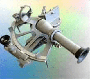
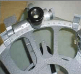
The nautical sextant is a double-reflecting angular instrument. Its operating principle relies on the optical law that when a ray of light is reflected consecutively from two plane mirrors in the same plane, the angle between the first incident ray and the last reflected ray is twice the angle between the planes of the two mirrors.
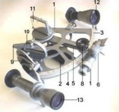
Component Specification:
2. Telescope Collimation Error (Optical Axis Parallel to the Arc)
The optical axis of the viewing telescope must be strictly parallel to the plane of the graduated arc. If non-parallel, measured altitudes will always read higher than their true values.
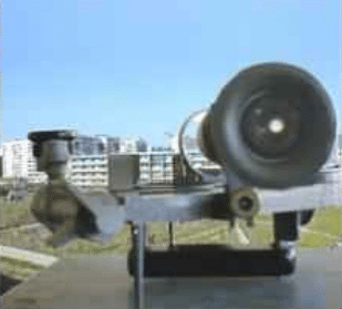
- Place the sextant horizontally on a firm, level surface (e.g., its wooden carrying case).
- Position the index arm roughly near the midpoint of the arc (around 60°).
- Place two parallel sighting vanes (diopters) onto the ends of the arc so the line connecting their upper edges runs approximately parallel to the telescope axis.
- Select a distant mark at least 50 meters away, positioned at about the same horizontal level. Orient the sextant so that the target’s horizontal edge aligns with the top of the vanes.
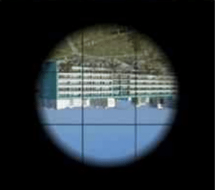
- Look through the telescope: if the horizontal line does not sit directly in the center of the reticle square, adjustment is required.
- Use an adjusting screwdriver to turn the top and bottom screws on the telescope collar (slackening one while tightening the other) until the target line settles exactly in the reticle center.
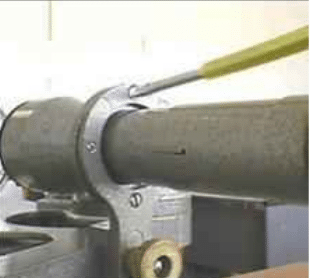
Note: Star telescopes on standard marine sextants frequently lack collar adjustment screws, as factory tolerances are fixed for low-power optics.
3. First Adjustment: Perpendicularity of the Index Mirror
The Index Glass must be strictly perpendicular to the plane of the instrument arc. If tilted, turning the index arm introduces a variable error across the entire arc.
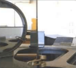
- Remove the telescope and place the sextant horizontally on a table.
- Set the index arm to approximately 40°–45° on the arc.
- Place two sighting vanes on the limb: one near 5°–10°, the second near 120°–130°.
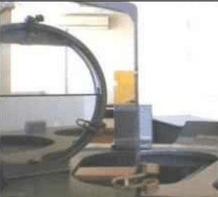
- Position your eye about 30–40 cm away from the index mirror at the level of the top of the vanes. Observe the reflected image of the right vane in the index glass right next to the direct view of the left vane.
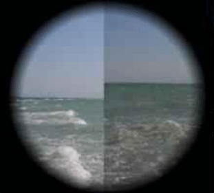
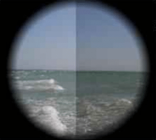
- Shift the right vane slightly until both images touch. If the top edges show a broken step, the index mirror is not perpendicular to the frame.
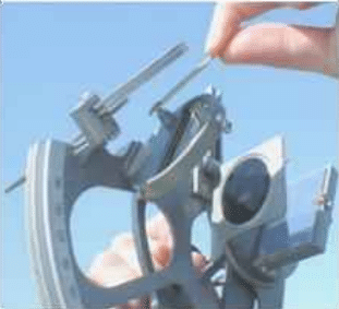
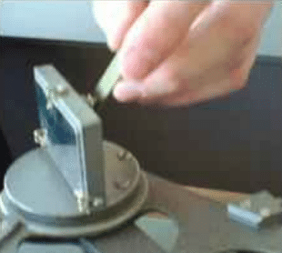
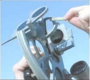
- Using the adjusting pin or socket wrench, carefully turn the screw on the back of the index mirror frame until the top edges form an unbroken, continuous line.

4. Second Adjustment: Horizon Glass Perpendicularity (Eliminating Side Error)
This adjustment must only be carried out after confirming that the index glass is true. If the horizon mirror is tilted relative to the arc, side error occurs: the reflected image of a celestial body will sit to the left or right of the direct image rather than directly above or below it.
- Set the index arm and micrometer drum near 0° 00.0′.
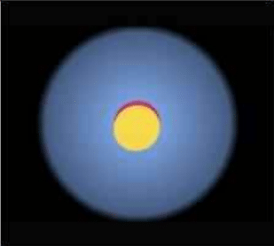
- Direct the telescope toward a distinct star or the Sun (ensure protective shade filters are flipped in place for solar sightings).
- If the reflected image is displaced diagonally from the direct image, turn the micrometer drum to bring them level horizontally.
- Using the adjusting pin, turn the side adjustment screw (the screw furthest from the frame on the back of the horizon glass) until the reflected image shifts sideways and merges onto the same vertical axis as the direct image.
Note: Turning the side screw often slightly changes the vertical alignment. Therefore, you must re-check index error after removing side error.


5. Practical Methods for Determining Index Error (i)
Even with both mirrors perpendicular to the frame, they may not be strictly parallel to one another when the alidade reads 0° 00.0′. This residual angular misalignment is called index error. The correction applied to cancel this error is the index correction (i).
Preparation is identical for all three methods: focus the telescope, set the index arm to roughly 0°, and inspect the horizon or body.
Method A. Determining Index Error by the Sea Horizon
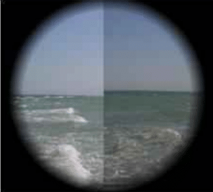
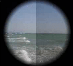
Point the sextant at a sharp sea horizon. If the horizon appears broken by a vertical step, turn the micrometer drum until the direct and reflected horizons merge into a single continuous straight line.
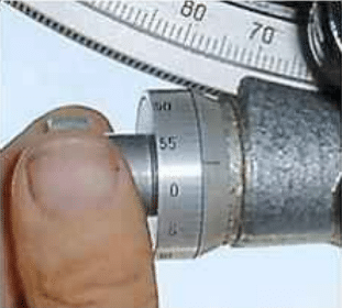
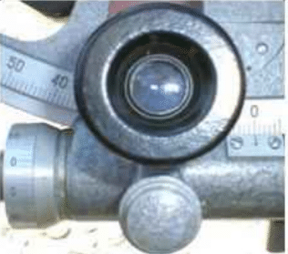
Read the observed index reading (oi) on the arc and drum. The index correction is calculated as follows:
Calculation Example: The observed index reading is oi = 0° 02.9′ (reading is on the arc). Therefore: i = 0° – 0° 02.9′ = -2.9′ (“If it is on the arc, it is off; if it is off the arc, it is on”).
Method B. Determining Index Error by a Star
Select a moderately bright star at low to medium altitude. Direct the telescope at the star with the alidade set near zero. Turn the micrometer drum until the reflected star and direct star merge into a single pinpoint of light. Read the value oi and calculate correction i.
Method C. Determining Index Error by the Sun (with Almanac Quality Check)
The solar method provides an internal mathematical quality check, ensuring observation reliability.
- Flip suitable shade glasses in front of both mirrors to protect eyesight.
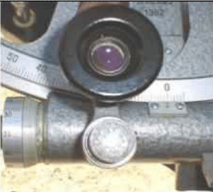
- Direct the telescope toward the Sun and turn the micrometer drum until the reflected disk touches the upper limb of the direct disk (reading oi1).
- Turn the micrometer drum in the opposite direction until the reflected disk moves across and touches the lower limb of the direct disk (reading oi2).


Formula for Solar Index Correction:
i = 360° – (oi1 + oi2) / 2
Accuracy Check: The absolute difference between the two readings |oi1 – oi2| = 4R equals four times the Sun’s semidiameter. Compare this result with 4 times the Sun’s semidiameter listed in the daily pages of the Nautical Almanac (4 × SD).
If the difference does not exceed 0.4′, the observations are mathematically verified and trustworthy. If the difference is larger, repeat the sight.
Take the excess over 30′ (as negative) or deficit under 30′ (as positive) for each reading. The half-sum of these deviations yields index correction i instantly.
In our example:
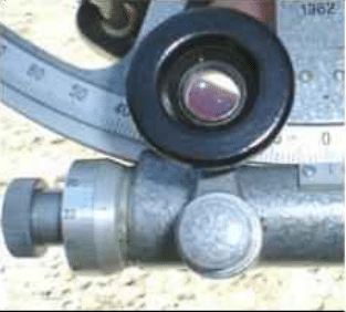
First reading 33.2′ yields an excess of -3.2′.
Second reading 29.3′ yields a deficit of +0.7′.
i = (-3.2′ + 0.7′) / 2 = -2.5′ / 2 = -1.2′.
6. Physical Reduction of Excessive Index Error
An index error does not alter observation accuracy as long as it is systematically applied. However, good navigational practice dictates that index error should not exceed 3’–5′ to prevent computation mistakes. If larger, reduce it mechanically.
- Set both the alidade and the micrometer drum precisely to 0° 00.0′.
- Point the telescope toward a distinct horizon.
- The direct and reflected horizons will show a vertical offset (step).
- Using the adjusting tool, turn the top screw on the horizon glass frame (the screw closest to the top of the mirror) until the reflected horizon aligns smoothly with the direct horizon.
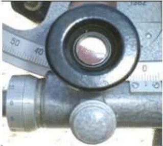
- Always measure and record the residual index error after completing any mechanical adjustment.